- 01UNO R4 5 V
- 02Trigger D7 / echo D8
- 03Resistors + LEDs
- 04Common GND
Match the board and module
The Elite Explorer family supplies an UNO R4 WiFi and learning components. Existing compatible parts also work. The main UNO R4 microcontroller uses 5 V GPIO. This wiring is not a pin-for-pin recipe for a Pico or ESP32, whose signal levels differ.
Wire with power disconnected
Identify the exact sensor module using its vendor guide. For the HC-SR04-style module covered here:
| Signal | UNO R4 WiFi connection |
|---|---|
| Sensor VCC / GND | 5V / GND |
| Sensor TRIG | D7 |
| Sensor ECHO | D8 |
| Red LED anode through 330 Ω | D4 |
| Yellow LED anode through 330 Ω | D5 |
| Green LED anode through 330 Ω | D6 |
| LED cathodes | GND |
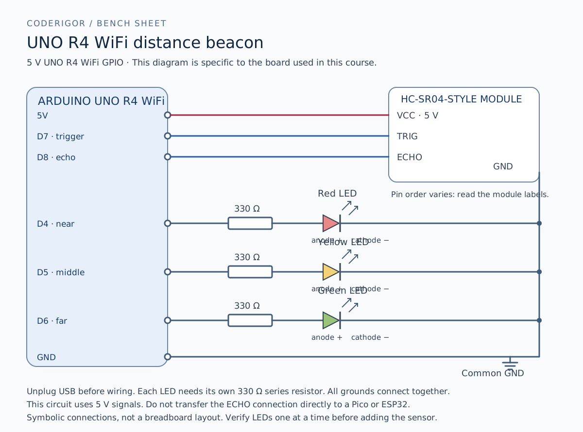
Open the printable wiring diagram. The same wiring.svg is included in the source download. This is a signal diagram; use the physical module's printed labels to find its pins.
Check the physical module's labels rather than guessing the four-pin order. Give each LED its own resistor. Use USB power for this small experiment; it does not use a relay, external motor or mains connection.
Install the UNO R4 board support through Arduino IDE's documented board manager and select UNO R4 WiFi, not UNO R3 or the ESP32 connectivity chip. Run Blink first to prove upload and port selection work.
Try it
Exercise each LED individually before connecting the ultrasonic sensor. A wrong LED pin should not be diagnosed by changing distance thresholds.