- 01Pico 3V3
- 02DHT11 on GP16
- 03LEDs on GP14/15
- 04Common GND
Choose the actual components
A Kepler kit is one bundled way to obtain a Pico W and learning components. You can use parts you already own. Check the package contents and module pin labels; do not infer pin order from the color of the sensor housing.
Connect with USB power unplugged
Use the vendor's breadboard and DHT11 diagrams to identify your parts. Our code uses GPIO numbers, not the physical header pin numbers:
| Connection | Pico W side |
|---|---|
| DHT11 supply | 3V3(OUT), physical pin 36, subject to the module's specification |
| DHT11 data | GP16, physical pin 21 |
| DHT11 ground | GND, for example physical pin 23 |
| Green LED anode through its own 330 Ω resistor | GP14, physical pin 19 |
| Red LED anode through its own 330 Ω resistor | GP15, physical pin 20 |
| Both LED cathodes | GND |
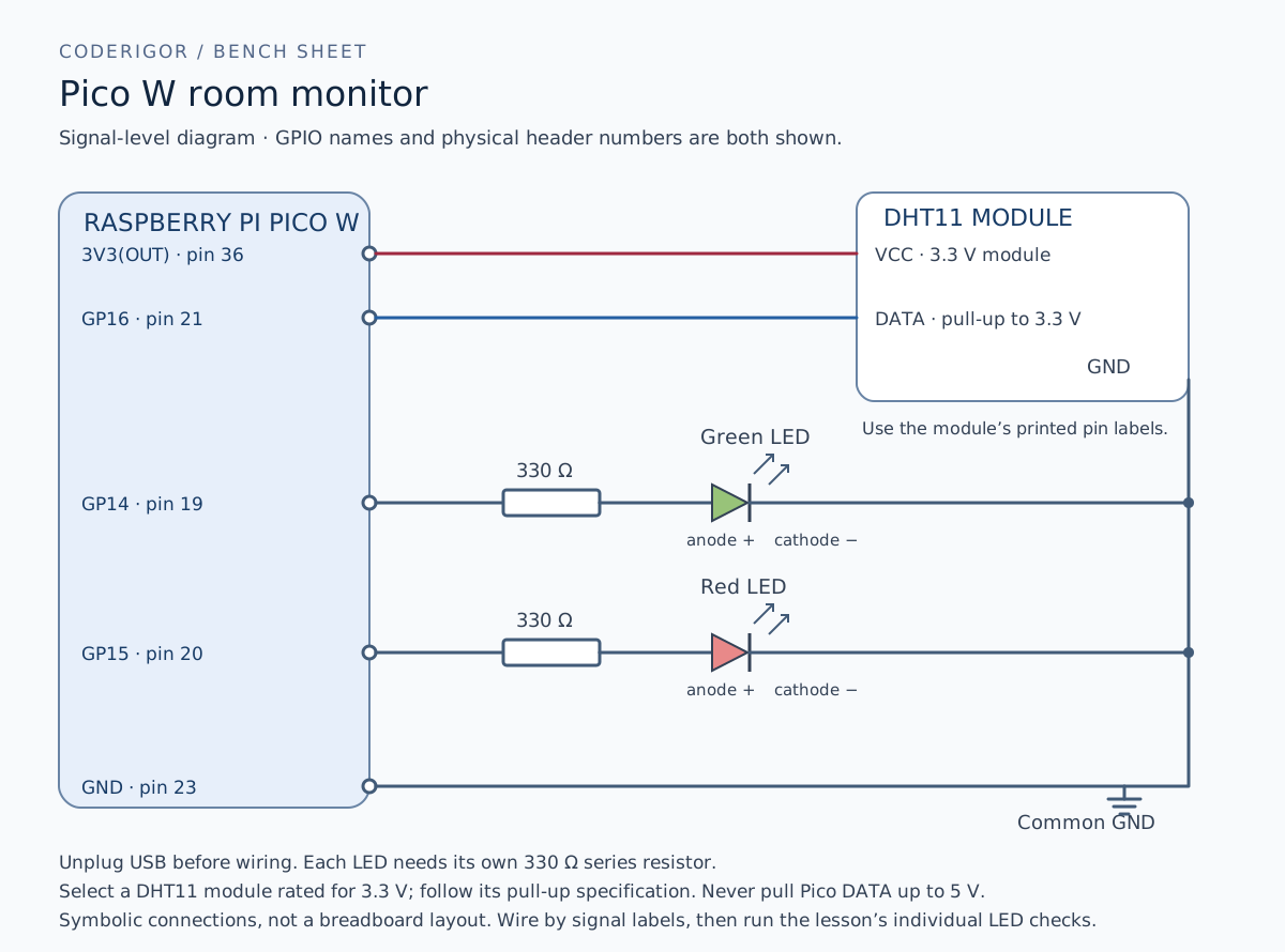
Open the printable wiring diagram. The same wiring.svg is included in the source download. Connections are symbolic; follow the module's printed labels rather than treating their position in this drawing as its physical pin order. Header numbers follow the official Pico W pinout.
Pico GPIO is a 3.3 V signal interface. Keep a data pull-up at 3.3 V. Some DHT11 modules include the pull-up; a bare sensor needs the arrangement specified in its datasheet. Do not connect a 5 V pulled-up data signal directly to the Pico.
Flash the official Pico W MicroPython image using its documented BOOTSEL workflow, then open the REPL in Thonny. Pico, Pico W and Pico 2 firmware files are not interchangeable choices. Verify the board identity before copying application files.
Try it
Blink one LED from the REPL, then the other. If neither works, check polarity, common ground, resistor placement and the GPIO/physical-pin distinction before adding the sensor loop.